Finite State Machines
A Finite State Machine (FSM) is a mathematical model used for describing how a system flows through a pre-planned set of steps. The intent of an FSM description is something like a flow chart but with different conventions for how it is written.
Each step is called a state and defines what output the system has at a particular point in time. A valid FSM could be comprised of a simple list of instructions that are followed in order one after the other but FSMs that are used in practice are often more complex than this. At each state a decision can be made based on inputs to the system. If one set of inputs are present then the FSM moves to one state and if another set of inputs are present then the FSM moves to a different state. The movement from one state to another is called a transition.
Each state is usually assigned a unique number or label. Every state the machine may possibly be in is fully planned in advance by the developer and the machine may only ever be in one state at once. The set of states that exist is finite, meaning the exact number of states the machine can have is known to us and we can easily count them all. This is not always the case with other kinds of software and many programs can result in a theoretically infinite number of states, although in practice on a real computer the software cannot really have infinite states as it will ultimately run out of memory and fail.
Despite being called a "machine", these days an FSM is most usually a piece of software running on a computer but it can also be a physical machine and FSMs are also commonly implemented as electronic circuits.
Example
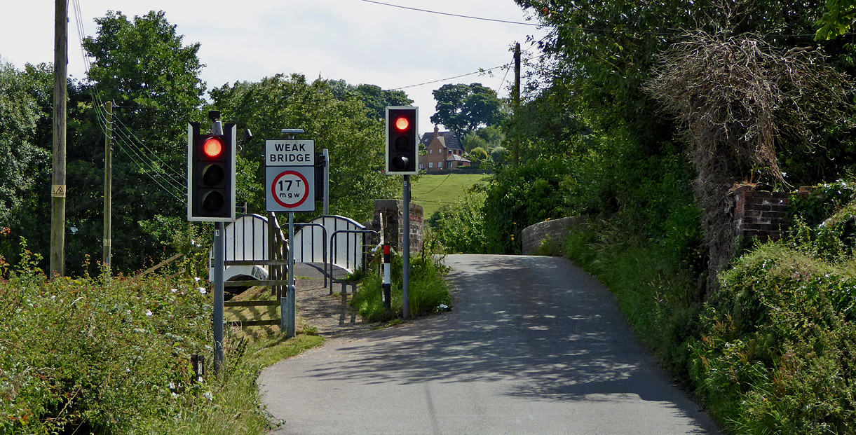
A Finite State Machine can be used to control a set of traffic lights. Imagine a pair of lights controlling access to a narrow bridge where there is only space for one car to pass at once.

The lights must be moved through a sequence of colour changes in a specific order from red to amber to green and back again. The system must also wait for various periods of time between the light changes. Each combination of traffic light colours can be defined using a state.
The set of states for the traffic lights looks like this. Each state has a unique number.

The traffic light states shown here follow UK conventions and different countries have slightly different sequences of lights. In the UK system amber means "stop if safe to do so" and an amber together with red means "prepare to go".
The traffic light control system starts at state 1 and then cycles through the states in sequence, performing the light colour changes or waiting period specified at each state. When it reaches state 8 it returns to state 1. A counter records the state number the FSM is currently at in the sequence.
In this example, each state has only one possible transition to the next state and we just go around in an infinite loop. However, it is possible for each state to have many different transition possibilities to other states depending on inputs to the system that happen at each state.
Say for example the traffic lights had a sensor that determined if a car was travelling on the bridge. When there were no more cars, we could change the lights to allow travel in the opposite direction to avoid unnecessarily delaying drivers. Below is the first part of the state diagram adjusted to account for this more sophisticated system:

Here we have introduced a new state 1A into the diagram. Firstly, we always wait 10 seconds regardless to allow waiting drivers time to react to the light change and move their vehicles onto the bridge. After this delay there is a transition from state 1 to 1A. State 1A does not change the colour of the lights but instead watches for a different set of conditions at the inputs. One transition loops around back to state 1A continously if the sensor detects a car on the bridge to hold the lights at green in anticipation of more traffic. However, there is also a transition such that if the sensor fails to detect a car (indicating no more traffic in that direction), then it begins the process to change the direction of the lights. Ultimately we have a timeout of 20 seconds, such that if there is very heavy traffic in one direction then the lights are changed regardless to allow even use of the bridge by both directions.
We could also use more states to add a pedestrian crossing controlled by a button. In this version, when the lights in both directions are on red and three seconds has been allowed for the bridge to clear of cars, we check if the pedestrian button has been pushed. If so, then we take an alternative branch. The green pedestrian signal is lit and time is allowed for pedestrians to cross. The pedestrian light turns red again and we continue with the traffic light states for the cars as previously. However, if the pedestrian button was not pushed, then we skip directly to the next phase in the light colour changes.

The above state diagrams are describing a Moore Machine type of FSM. Note that there are also other kinds of FSMs that work differently. Another common type is a Mealy Machine.
Image Credits: Car diagram, by Inkwina, Creative Commons Attribution-Share Alike 3.0 Unported; Traffic Light diagram, by Manuel Strehl, Creative Commons Attribution-Share Alike 2.5 Generic; Traffic light controlled bridge photo, by Roger D Kidd, Creative Commons Attribution-Share Alike 2.0 Generic